Ericsson Microwave Outlook
Executive summary
High- and mid-band deployments, but especially the latter, will drive backhaul needs in the future.
As capacity requirements in mobile networks become more diverse, so will demands on backhaul transport networks.
In this year’s report, we have updated the backhaul capacity table structure to highlight variations in requirements
for several spectrum strategies and site types.
Coexistence with other radio services in parts of the 6–15 GHz range is a hot topic in backhaul spectrum,
in order to cater for increased spectrum needs for mobile networks.
Long-range microwave backhaul is essential in these bands, both today and in the future.
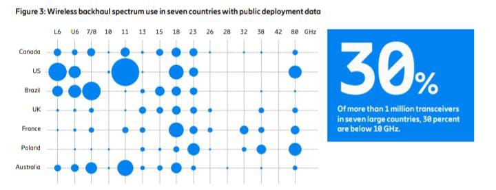
For example, around 30 percent of all transceivers are below 10 GHz in the countries studied,
but it varies per country from around 10 percent to more than 60 percent.
Microwave technology is continuously evolving to meet new requirements.
Modernized microwave planning and even more efficient spectrum use will play a significant role in achieving this.
It involves new key performance indicators (KPIs) and more balanced dimensioning that,
without negatively impacting quality of experience (QoE), can enable longer hop lengths,
higher capacity, improved energy savings and lower spectrum costs.
More aggressive frequency reuse enables wider channels, which results in higher capacity
and more efficient spectrum use.
Interference management in subnetworks can be a future step to enable prioritization between links and ensure
that links operate efficiently.
Security is a topic that is rightfully high on everyone’s agenda, and security in microwave networks is,
for the first time, covered in this report.
Microwave nodes are frequently located in remote, unsupervised locations which can be susceptible
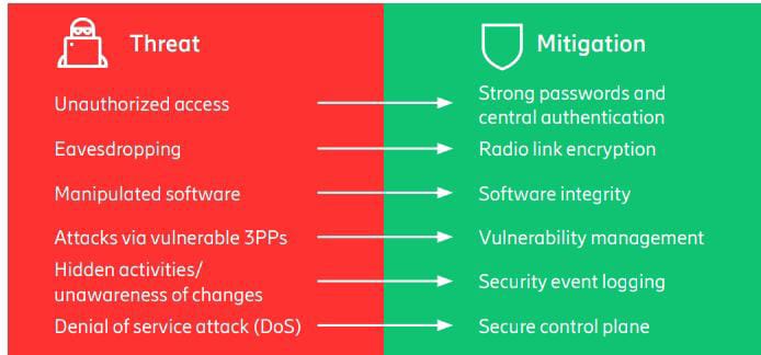
to unauthorized access, and the possibility of eavesdropping, ingestion of manipulated software,
attacks via vulnerable third-party providers, hidden activities and denial of service attacks.
Communications service providers can mitigate these threats in several ways, as covered in the report
Backhaul capacity evolution
The expansion of 5G is continuing. It is now forecast to pass 4G to become the dominant mobile access technology
by subscription in 2028 and to account for 60 percent of all mobile subscriptions by 2029.
To date, around 300 service providers have launched commercial 5G services
and it is forecast that 75 percent of mobile data traffic will be served by 5G in 2029.
5G population coverage outside of mainland China has now reached around 40 percent,
but with large regional variations where some markets are at around 10 percent.
Global 5G population coverage is expected to increase significantly to up to 80 percent
by the end of 2029, creating the potential for significant user data throughput increases.1
In most markets, with the exception of Europe, mid-band population coverage matches 5G population coverage
reasonably well.
As 5G coverage increases, so will deployments of mid-band.
Today, high-band is more sparsely deployed and mainly found in the US.
Deployment of high-band will also increase, but more selectively than mid-band
and with a focus on urban environments.
In around 2030, we will see the introduction of 6G and this is expected to lead to more spectrum
being released in the mid- and centimeter wave (cmWave) bands pending decisions at World Radiocommunication Conference 2027 (WRC-27).
As it is too early for detailed analysis of these proposed new bands,
they are not included in this year’s capacity table.
For more on 6G spectrum, see the Ericsson white paper ‘6G spectrum – enabling the future mobile life beyond 2030’.2
Both mid-band deployments, with a large amount of spectrum and a high MIMO layer count,
and high-band deployments, will enable a significant increase in user throughput, driving backhaul needs.
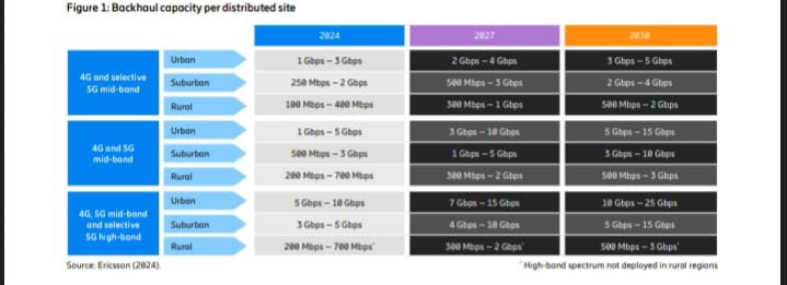
Typical backhaul capacity requirements for distributed Radio Access Network (RAN) sites are shown in Figure 1.
The table shows how variations in backhaul capacity
requirements between regions, markets and service providers continue to be significant and are even increasing.
These variations are the result of differences in service provider spectrum holdings,
actual service provider spectrum deployments and deployed RAN features, such as carrier aggregation.
Increased deployment of mid-band is expected to have the largest overall impact on the network,
as it will be used in all regions and deployment areas.
Some of the reasoning behind the formulation of the table can be found in the Ericsson blog
‘Backhaul end-site capacity: Guesswork or science?’.3
As backhaul capacity needs in mobile networks become more diverse,
so will demands on backhaul transport networks.
Both high capacity and flexibility will be needed to cover lower-bandwidth deployments efficiently.
A thorough analysis of mobile network performance targets is key to finding the correct backhaul dimensioning
Spectrum, a shared gem
Microwave and millimeter-wave spectrums are key assets for the wireless backhaul of 5G,
and beyond, with around 10 million transceivers installed around the world.
Different frequency bands are used to provide critical transport network infrastructure in all areas,
from dense urban to deep rural areas, for ranges from hundreds of meters to beyond 100 km.
The traditional bands, 6–42 GHz, remain the backbone for (point-to-point) wireless backhaul, as shown in Figure 2
A remarkable journey
The E-band (80 GHz) has been on a remarkable journey over the last decade
and is now extensively used as a 5G backhaul band.
In recent years, there has also been a rapid maturation of radio technology for beyond 100 GHz.
Today, there are regulatory recommendations on channel arrangements,
ongoing equipment standardization and pre-commercial wireless backhaul equipment available
for trials in the W-band (92–114 GHz).
Both W-band and D-band (130–175 GHz) are untapped high-capacity spectrum
resources for the future wireless backhaul demand
Coexistence in 6–15 GHz
Spectrum is a scarce and very valuable resource.
Spectrum sharing and coexistence capabilities are becoming more important than ever
due to the demand for more spectrum for different types of wireless broadband use,
with technologies such as 5G/6G, Wi-Fi, satellite and wireless backhaul.
Opportunities for coexistence in parts of the 6–15 GHz range is the latest hot topic in backhaul spectrum,
as shown in Figure 2.
Access to spectrum can be achieved in different ways, such as through the ITU World Radiocommunication
Conferences (WRC), regional decisions, or decisions on a per-country basis.
Whichever method is pursued, harmonization of the selected frequency bands and technical conditions,
ideally on a global or at least a regional basis, is key to unlocking economies of scale
and to provide numerous benefits to consumers and enterprises.
Some countries have allocated 5.925–6.425 GHz (lower 6 GHz) for unlicensed use,
also known as license-exempt, including Wi-Fi and 5G NR-U (NR in unlicensed spectrum).
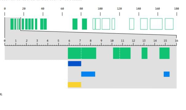
A few countries, such as the US, have expanded this allocation up to 7.125 GHz.
Although technical conditions have been established with the aim of protecting incumbent wireless backhaul,
introducing unlicensed use in a licensed backhaul band raises some concerns.
There continues to be debate about whether the backhaul is sufficiently protected in worst-case scenarios.
The Electronic Communications Committee (ECC) is also studying the impact of a bursty interference,
such as Wi-Fi beacon signals.
It remains to be seen what impact the growing use of unlicensed 6 GHz Wi-Fi
devices will have on the incumbent licensed wireless backhaul use
And if interference issues arise, how will they be resolved,
as unlicensed spectrum is not controlled?
International harmonization
The WRC in 2023 (WRC-23) decided on an international harmonization of the upper 6 GHz spectrum,
6.425–7.125 GHz (or parts thereof), for International Mobile Telecommunications (IMT).
This is the generic term used by ITU for mobile systems, such as 5G.
The decision had support from countries representing 60 percent of the global population,
and more countries are expected to support this at the next WRC in 2027.
The intention of identifying a frequency band for IMT is to provide equipment manufacturers
with guidance on which spectrum may be made available for mobile services,
while leaving the final decision on implementation up to each nation
WRC-23 also decided on the agenda items for WRC-27.
One agenda item is to consider studies on sharing and compatibility
and develop technical conditions for the use of IMT, which includes the bands 7.125–8.4 GHz (or parts thereof),
and 14.8–15.35 GHz.
These bands have a large overlap with the 7, 8 and 15 GHz wireless backhaul bands (see Figure 2).
Notably, in addition to the decisions taken at WRC-23, an initiative in the US included 7.125–8.4 GHz
in the National Spectrum Strategy to be studied for wireless broadband use.
For more comprehensive information on 6G spectrum, see the Ericsson white paper.
Long-range wireless backhaul use
It is interesting to look at wireless backhaul use in the 6–15 GHz bands today,
as well as considering future demand.
These bands, especially 6–8 GHz, are essential for long-range wireless backhaul
due to their superior propagation characteristics for distances from about 20 km to beyond 100 km.
These are typically used in rural areas and for connecting them to urban centers.
A global and regional overview of the use of wireless backhaul spectrum
can be found in the Ericsson Microwave Outlook 2022,2 reporting around 10 million transceivers globally
National usage of wireless
backhaul spectrum Some countries have public data onwireless backhaul installations,
which can be used for a deeper analysis.
Figure 3 shows national usage of wireless backhaul spectrum in seven large countries around the world.
The size of each circle represents the installed base of transceivers,
with in total more than 1 million for these countries.
There are large variations in how much each backhaul band is used in different locations,
countries and regions.
Many of the bands are used in most countries, but the relative use varies.
For example, 30 percent of all transceivers in Figure 3 are used for the essential long-range bands in 6–8 GHz,
but it varies per country from around 10 percent to more than 60 percent.
This depends on the local demand and historic decisions on what
is the most valuable use of a frequency band in each region and country.
One example is the 11 GHz band, (10.7–11.7 GHz),
which some countries have prioritized for extensive wireless backhaul use,
while others have prioritized it for uncoordinated satellite earth station (receiver) use with no,
or very restricted, wireless backhaul use.
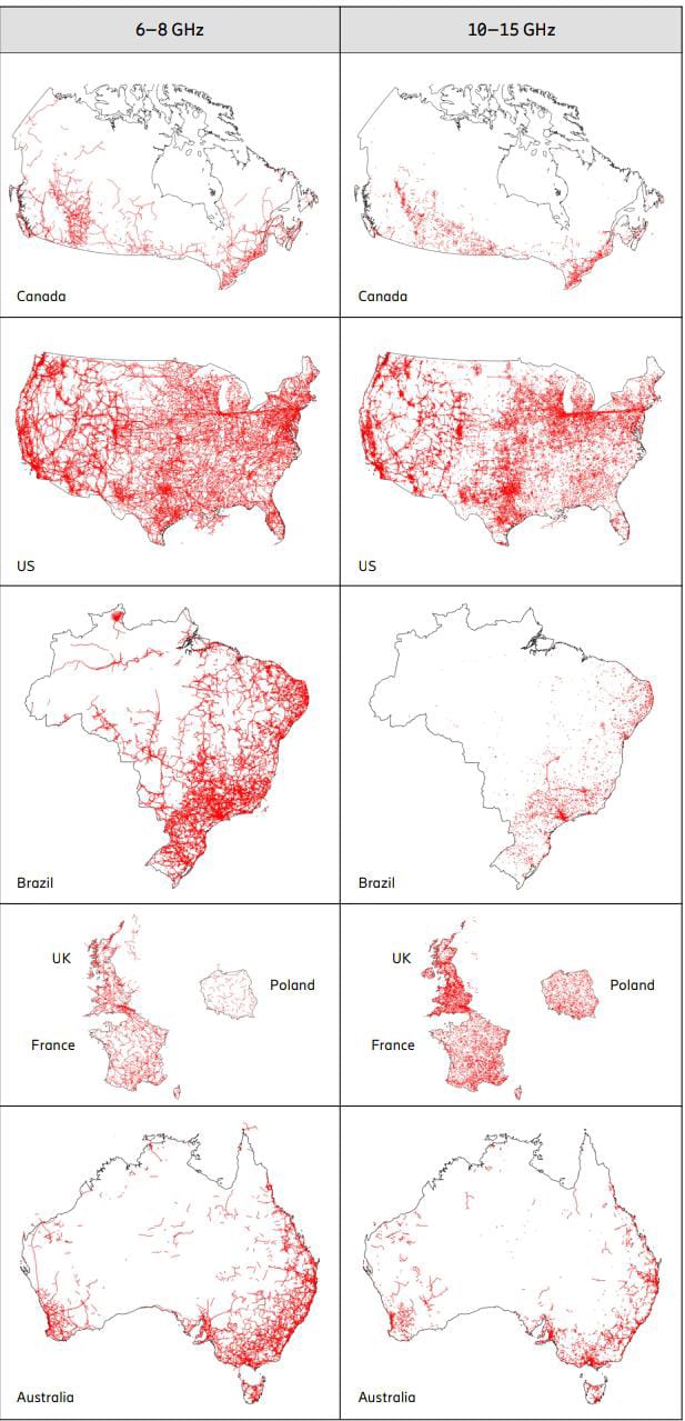
Figure 4 shows a useful geographical overview of the wireless backhaul deployments
for the bands in each of these countries.
Each red line corresponds to a point-to-point wireless backhaul link.
The 6–8 GHz bands, or parts thereof, are used for long-range wireless backhauling in all parts of these countries,
except for the most remote rural areas where there are few people and no terrestrial transport networks.
The 10–15 GHz bands are useful for shorter distances and therefore are used closer to urban centers.
Importance of coexistence
How much these bands are used also depends on the penetration of fiber transport networks in these countries and areas.
Even if there are many advantages of fiber transport,
it is simply too costly and not sufficiently reliable to be used in all locations.
Spectrum in the 6 GHz band, as well as 7–15 GHz bands, is being considered
by national regulators for the future growth of mobile networks.
Notably, mobile systems are less challenging in terms of coexistence with incumbent wireless backhaul,
which is in fixed known locations, uses passive antennas with very narrow beamwidths,
and features such as automatic transmit power control (ATPC) that further reduce any interference.
The licensed nature of mobile and backhaul allows for coordination, including geographical coordination.
Conclusion
Wireless backhaul is a somewhat “unsung hero” that has helped to enable the current global communication
networks.
It is important to carefully consider the extensive
and essential use of long-range wireless backhaul in these bands – today, as well as tomorrow.
Introducing unlicensed use raises many concerns, while there are opportunities
for coexistence with licensed mobile systems.
It is expected that the most valuable use of a frequency band will also, in the future,
vary in different regions, countries and locations.
Trusted microwave networks
The security of a microwave transport network can be compromised in a multitude of ways.
For example, full network access could be mistakenly given to contract workers hired
to do a limited site upgrade. Perhaps a disgruntled former employee has access to team login credentials.
A curious hacker could be exploring known Linux/open source vulnerabilities.
Or, accidental access could be obtained by a used equipment trader
who logs in to scrapped equipment that contains network information by testing default login credentials.
In recent years, the industry has responded to these potential risks by initiating
and increasing focus on implementing vulnerability management processes
and developing secure software and hardware architectures.
The active involvement of standardization bodies, such as the National Institute of Standards
and Technology (NIST) and the Cybersecurity and Infrastructure Security Agency (CISA) in the US,
and the National Cyber Security Centre (NCSC) in the UK,
has also resulted in recent releases of various requirements and documents for network security.
Threats and their mitigation in microwave networks
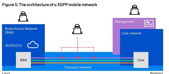
In Figure 5, the architecture of a 3GPP mobile network is shown, consisting of a Radio Access Network (RAN)
with radio units (RU), distributed units (DU) and central units (CU) deployed in local sites,
and the Core network deployed in a handful of national locations.
The RU, DU, and CU are often located in unsupervised sites that may be exposed to unauthorized access,
while the Core network is placed in high-security, data center-like locations.
The transport network connects the RAN with the Core network
and often consists of a mix of physical technologies,
such as optical and microwave links that are able to cover long distances with many nodes.
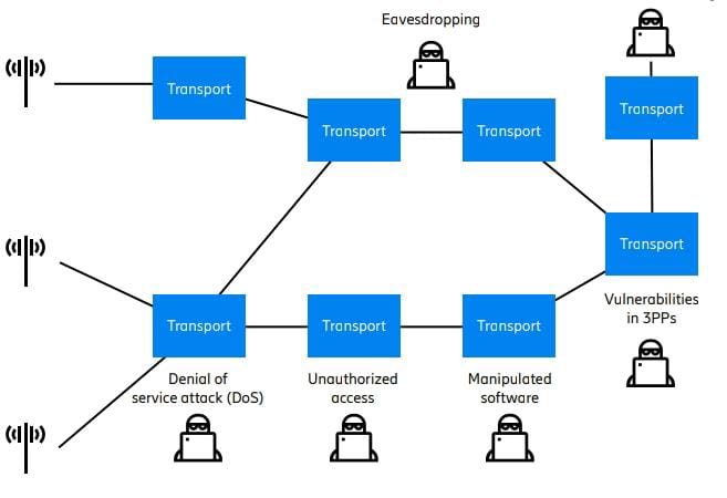
The nodes are frequently located in remote,
unsupervised locations which can be susceptible to unauthorized access,
thereby providing possibilities for eavesdropping, ingestion of manipulated software,
attacks via vulnerable third-party providers (3PPs), hidden activities and denial of service attacks (Figure 6).
Unauthorized access
In this article, an unauthorized access event is defined
as one where a user without access rights gains admission to information
or configuration rights in a node or a network by having access to physical hardware or login credentials.
To mitigate this, it is essential to implement strong access control policies with a centralized authentication process
requiring individual, strong passwords that are frequently updated,
and for this to be combined with multi-factor authentication.
Future enhancements are being discussed across the industry to make it more difficult
for external sources to access unauthorized information directly through physical hardware.
For instance, to prevent intrusion by probing memory chips
or the communication lines between different chips on a printed circuit board,
the hardware should be built on a trusted hardware architecture.
The intent is that components in the system should have a wall of protection against
other components in the system, which prevents unauthorized access to the complete system
if one component becomes implicated.
This could, for example, mean that communication between hardware components is encrypted and that data is authenticated.
An intuitive way to understand the difference between a common hardware architecture
and a trusted hardware architecture is a comparison between a coconut and a pomegranate.
The coconut has a hard shell protecting the content inside but once the shell is penetrated,
it is possible to access its content. The pomegranate, on the other hand,
has protective shells around all components within its outer shell.
Eavesdropping
The signal in a microwave network is similar to the signal from the RAN,
propagating through an unprotected medium, namely the air,
but it is still a rather complex task to intercept the traffic in mid-air.
It requires detailed knowledge about the transmitted signal such as the frequency, modulation,
data rates and coding of the transmitted data, which is proprietary to each vendor.
Still, data encryption is recommended to protect the network from eavesdropping.
End-to-end encryption, specifically encryption and decryption in the Core network and the RAN nodes,
is the recommended solution.
It is also transparent to individual proprietary link technologies,
ensuring the information remains encrypted throughout the full transport network.
Another option for microwave is radio link encryption, which encrypts the signal
and provides the benefit of being impossible to detect if or when the radio link is being used.
However, if only radio link encryption is used,
there is still a vulnerability at each node where decrypted information may be monitored
if an unauthorized user is getting access to the node.
Hence, the recommendation is to have end-to-end encryption
with the option to add radio link encryption to protect the network even further.
Manipulated software
A complex threat involves the intentional manipulation of firmware running on microwave nodes.
To address this, the microwave vendor must secure software integrity through automatic
or manual updates of software from trusted sources, using secure protocols.
Furthermore, it is important to implement solutions that can secure the trust of the updated software,
such as ensuring users of systems can be certain that downloaded and booted software is not altered in any way,
and that it is digitally signed by the microwave vendor.
Attacks via vulnerable 3PPs
Nowadays, 3PP software components, such as Linux distributions and 3PP network stacks,
are an integral part of modern software development.
Vulnerability management – including control, tracking, assessment of impact
and mitigation of known and recently detected vulnerabilities in the 3PP software components – is, therefore,
crucial, as information about these vulnerabilities can quickly spread and provide simple
and straightforward opportunities for attackers to target and explore.
Microwave vendors should have a clear strategy for discovering,
tracking and addressing vulnerabilities in their equipment as part of their product development life cycle
and a well-defined process for sharing known vulnerabilities with service providers.
This strategy must comply with standards such as the 3GPP Network Equipment Security Assurance Scheme,
monitored by organizations like GSMA
Hidden activities/unawareness of changes
To limit the impact of an intrusion, it is of the utmost importance to detect attacks and security vulnerabilities as soon as possible.
One example is the detection of intentional or unintentional changes in security settings
that may lead to malicious activity, such as hidden configuration changes of the node.
To mitigate this, it is necessary to support security event logging on the microwave nodes,
which enables visibility of security events and activities.
Denial of service (DoS) attack
In a DoS attack, a node is flooded with requests, the aim being to make the node inaccessible
and thereby impact network performance.
To mitigate this, microwave nodes should have the ability to enable policies in the control plane
to prevent the build-up of request queues, which ensures that the network node continues to operate.
One option for achieving this could be a policy allowing the service provider to
configure a quality-of-service filter that manages the traffic flow of control plane packets
to protect the microwave node.
Securely configured microwave nodes are essential for the proper operation of microwave networks,
and both vendors and service providers play vital roles in ensuring that the necessary security functions
and hardening measures are in place.
Conclusion
This article provides insights into the rapidly evolving security landscape and highlights some common security
threats and their mitigations,
which are summarized in Figure 7.
Service providers can mitigate these threats through diligent security configurations,
and should also consider security features when selecting hardware.
Future security improvements may involve changes in trust boundaries, requiring comprehensive security design
and secure communication between internal platform components.
Overall, building reliable microwave networks requires both collaboration
and standardization to address security challenges and enable swift adaptation to evolving security requirements
The future of microwave planning
Microwave technology is evolving continuously to meet new requirements set
by the latest generations of radio access technologies and new use cases.
As capacity boundaries are pushed further, it is important to maintain sustainable requirements
which involves more balanced dimensioning.
Additionally, access to more spectrum, wider channels and high spectrum efficiency are key for achieving higher capacity.
More aggressive frequency reuse combined with interference management is a way to improve spectrum efficiency.
Benefits of more balanced dimensioning
Traditional microwave planning methods date back to the introduction of circuit-switched 2G (GSM) networks,
which were mainly deployed to provide voice services to mobile users.
The first generation of microwave links used a single, fixed modulation,
and it was therefore natural to plan the links based on strict availability targets.
This meant that a link should have a high likelihood of supporting the voice services it carried –
some 99.999 percent of the time – since if the link was down, then voice services were also down.
With the adoption of packet-switched networks for data in 3G, together with adaptive coding
and modulation (ACM) in high-capacity microwave links,
the need for such extreme availability for all ACM levels became unnecessary.
Instead, differentiated availability with different availability targets for different ACM levels became more significant.
In practice, differentiated availability means that lower modulation levels have higher availability targets
than the higher modulation levels.
A high availability target (for example, 99.99x percent) on a committed information rate (CIR)
ensures that services like voice and other high-priority service and control operations are guaranteed,
while a lower availability target on peak information rate (PIR) allows for traffic peaks
that occur more rarely.
It is also not uncommon for it to be the radio access network (RAN)
that limits the bitrate and the user experience due to phenomena such as radio channel fading
, shadowing and interference.
A good strategy, therefore, is to dimension the microwave backhaul in balance
with the RAN traffic it carries to avoid unnecessary overprovisioning of the backhaul.
Excessively strict availability targets limit the possible use cases of microwave backhaul links.
By contrast, a well-balanced dimensioning opens several possibilities, including longer hop lengths,
higher capacity, energy savings and use of higher sub-THz frequencies.
As a step toward a more balanced backhaul dimensioning, ETSI ISG mWT has defined a new KPI called backhaul traffic availability (BTA).
Put simply, BTA is defined as the probability that the backhaul link capacity supersedes
the RAN traffic it carries, which is the same as the probability that the link is uncongested.
The BTA thus depends on the probability distributions of the backhaul link capacity and the RAN traffic.
BTA applies to all frequency bands, but it is especially interesting for E-band
and future sub-THz links since it leads to higher capacity over longer hop lengths,
both in single- and multi-band configurations.
The need for higher capacity over longer hop lengths is demonstrated
by the growing deployments of multi-band links.
On the topic of KPIs, standardized ITU-T definitions of user QoE also exist for different services.
QoE is defined by a service-specific function of user rates and delays in the user downlink
and uplink, and are typically represented by a QoE rating ranging from 1 to 5,
where, for example, 4.5–5.0 is excellent, 3.5–4.5 is good, 2.5–3.5 is fair, and so on.
Balanced dimensioning in action
To illustrate the benefits of more balanced backhaul dimensioning,
a simulation was conducted of a 5G RAN in the 3.5 GHz band serving mixed traffic types like video-on-demand,
web-browsing, live streaming, cloud gaming and augmented reality (AR).
The RAN comprised three sites with three sectors each,
with the aggregated traffic from all sectors being transported over a multi-band backhaul
link combining E-band and 18 GHz band in the Gothenburg, Sweden, rain zone.
The traffic load in the RAN varied between low (20 percent), medium (50 percent) and high (70 percent) utilization,
where utilization is set by the number of users within each user type,
with the AR users being the most resource demanding.
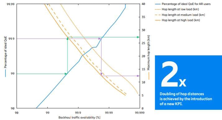
Figure 8 shows the result from the simulation investigating
the effect of BTA on QoE of AR users and the maximum possible hop length of a multi-band backhaul link.
The left y-axis shows the percentage of ideal QoE for AR users.
Ideal QoE means the maximum possible QoE attained by using an ideal backhaul that does not have any impact on user QoE.
Ideal backhaul can be interpreted as a backhaul with infinite capacity and 100 percent availability.
The ideal QoE, therefore, only depends on the performance of the RAN and not the backhaul.
The blue curve represents how a large fraction of the ideal QoE is attained
by using a multi-band backhaul link instead of an ideal backhaul.
For example, 99 percent of the ideal QoE for AR users implies that the QoE
for AR users is 99 percent of the maximum possible QoE attained by using an ideal backhaul.
It can be argued that this is an insignificant reduction from the maximum QoE
and that the AR users will not experience any negative impact during their sessions.
The right y-axis shows the maximum hop length of the multi-band backhaul link
as a function of BTA for the different RAN traffic load levels. The x-axis is common for all curves
and represents the BTA as defined by ETSI ISG mWT.
The lower the BTA, the higher the likelihood of congestion in the backhaul, and user QoE reduces correspondingly.
However, if a lower BTA and a correspondingly lower QoE is accepted,
then the maximum hop length can be increased. This is illustrated by some of the operating points in Figure 8,
where there is a clear connection between QoE, BTA and hop length. Take,
for example 99.9 percent of ideal QoE, which in the simulated case, corresponds to a BTA of around 99.98
percent at high load and is attained by a maximum hop length of 12.5 km
(which is illustrated by the purple arrows).
If 99 percent of the ideal QoE (corresponding to 99.77 percent in BTA) is accepted instead,
the maximum hop length can be more than doubled, to 27.5 km (which is illustrated by the green arrows).
In the ETSI Group Report, it is indicated that the optimum range for BTA values is between 99.5 percent
and 99.9 percent, but it is also recognized that the final choice is
up to the preferences of individual service providers and the needs of specific services.
It is important to emphasize that more balanced dimensioning
does not imply an increased risk of outage of critical services,
since the CIR is still associated with a high availability target like 99.99 percent to 99.999 percent.
It is rather that the PIR is associated with a more balanced availability requirement that matches the BTA.
When it comes to multi-band backhaul links like the one used in the simulation example,
CIR is provided by the low-band link while the PIR is provided by the E-band link.
It means that relaxing the PIR availability requirement of the E-band link only has a very minor,
if any, negative effect on user QoE while effectively resulting in more than two times longer hop length
Opportunity with interference management
Modern microwave links are very spectrally efficient, meaning that they provide many bits per second per Hertz (bps/Hz).
High spectral efficiency is ensured by successfully employing techniques like high-order modulation,
high-performance dual-polarized antennas (XPIC) and multiple-input, multiple-output (MIMO).
Microwave links also operate in regimes with high signal-to-noise ratio (SNR) thanks to efficient power amplifiers,
high-gain antennas and high receiver sensitivity.
This means microwave links are what is known as bandwidth-limited, meaning that their capacity is more limited
by the spectrum bandwidth than by their SNR.
Capacity grows linearly with bandwidth but only logarithmically with SNR,
which implies that it is more spectral-efficient to try and increase the bandwidth instead of SNR
when the link is in the high-SNR regime.
This is exactly what universal frequency reuse – or frequency reuse one (FR1) – sets out to achieve.
In FR1, all (or at least a majority of) links use the same frequency channel to allow wider channels to all links.
For example, instead of allocating four neighboring links a separate 28 MHz channel each,
they can all use the same 112 MHz channel which increases their possible peak rate by a factor of four.
The downside of using the same frequency channel is increased interference between the links.
However, since the links are in the bandwidth-limited regime,
the upside of more bandwidth is much larger than the downside of increased interference.
As with balanced dimensioning and BTA, a more relaxed availability requirement on peak rate has little,
if any, impact on user QoE.
Local traffic-aware transmit power control is an efficient way to limit interference between links in an FR1 network.
Traffic varies over both space and time across the network,
and local traffic-aware power control continuously adapts the transmission power of each link to the minimum
power needed to serve its immediate traffic needs.
This way, unnecessary interference is avoided in the network compared to using a fixed output power
or some other traffic-unaware power control.
Previous Microwave Outlook reports have shown
the large benefits of this type of local traffic-aware power control in FR1 networks.
However, if the interference between neighboring links is large, then the links may start competing for capacity
by raising their transmission powers in an uncontrolled manner, and such situations need to be avoided.
One simple way of avoiding power rushes is to consider this issue in the initial network planning phase,
for example, by setting caps on the maximum permitted transmission power of each link in the network based on interference models.
Another, more sophisticated way is to employ interference management
by using centralized power control combined with traffic prioritization.
For example, if multiple interfering links are competing for capacity
but one of them carries higher priority traffic than the others,
then a centralized controller can allocate or schedule more capacity to the high-priority link.
Many links also have a natural isolation between them, which limits the interference
and the need for centralized interference management. This isolation is mainly provided
by the narrow-beam antennas with low side-lobe levels.
To illustrate isolation between links and how many links may need centralized interference management,
the use of FR1 was simulated in a real backhaul network
with a very dense deployment of microwave links.
The simulation was used to investigate how to divide
the complete network into subnetworks based on interference levels.
The principle was simple: if two or more links interfered with each other over a predefined interference-to-noise (I/N) threshold,
then the links were allocated to the samemulti-link subnetwork.
If a link was not transmitting/receiving too much interference to/from other links,
then it could operate independently of all the other links in a single-link subnetwork.
Centralized power control and interference management is only required
when links in the multi-link subnetworks start to compete for capacity.
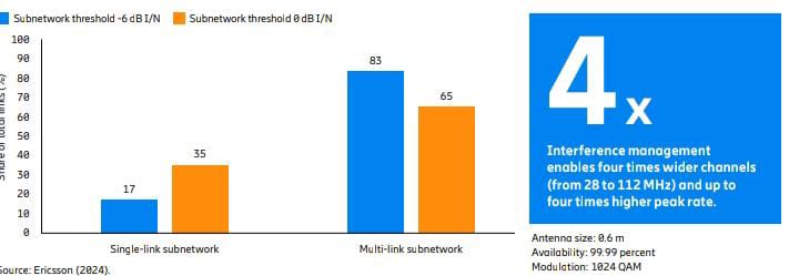
Figure 9 shows how a large share of the total links in a dense network, with close to 1,000 links operating
at 15 GHz, is allocated to single- or multi-link subnetworks.
In this example, the antenna size was 0.6 meters,
and the availability target was 99.99 percent at 1024 QAM.
Two I/N thresholds were assumed, -6 dB and 0 dB, respectively.
The higher the I/N threshold, the higher the number of links that can operate independently in a single-link subnetwork.
Meanwhile, a stricter (or lower) I/N threshold means that more links need to be allocated to multi-link subnetworks.
To illustrate the effect of using more narrow-beam antennas to provide more isolation between links,
the same network deployment was also simulated with E-band links.
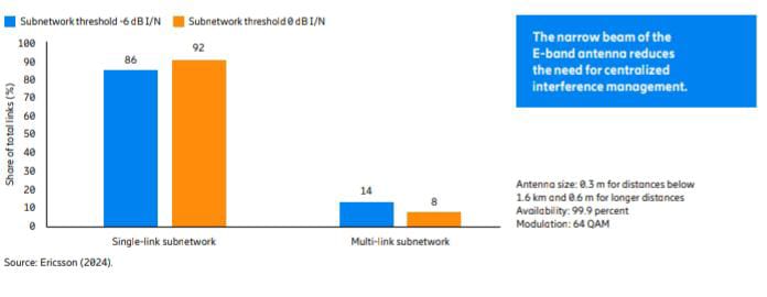
Figure 10 shows the share of total links allocated to single-link and multi-link subnetworks,
respectively. The narrow beam of the E-band antenna provides very good isolation between links,
which significantly reduces the need for centralized interference management since only 14 percent
and 8 percent (at the two different I/N thresholds) of the total number of links belong to a multi-link network.
This can be compared to the 15 GHz network in Figure 9,
where the equivalent shares were 83 percent and 65 percent, respectively
Conclusion
Modern microwave planning involves new KPIs and more balanced dimensioning
that can enable longer hop lengths, higher capacity, energy savings and lower spectrum costs,
without negatively impacting user QoE.
More aggressive frequency reuse, such as FR1, enables wider channels resulting in higher capacity
and more efficient spectrum use.
Interference in dense FR1 networks can be reduced effectively
by using local traffic-aware power control in all frequency bands.
The benefit of centralized interference management is more pronounced in the lower bands
than in E-band networks, as these have more isolation between links
which suffices for the use of local traffic-aware power control.


